![UK Argo [logo]](/themes/ukargo-NOC8X/logo.svg)
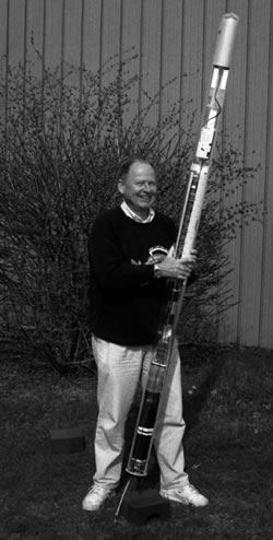
- The first floats were constructed and tested by Swallow and Stommel.
The concept of using neutrally buoyant floats that drifted at depth to elucidate more about ocean currents was first developed in the 1950s. The idea came about independently in the UK and the USA simultaneously (Swallow, 1955 and Stommel, 1955; respectively).
In the UK, John Swallow worked at the National Oceanography Institute applying his practical understanding of oceanography to develop, construct and test the first floats. Swallow realised that the original idea of tracking slowly sinking sonobuoys to derive current profiles would not work due to the compressibility of materials and seawater and the difficulty in making waterproof seals that could withstand deep-sea pressures.
Swallow therefore concluded that the floats should be designed to stabilise at some level within the water column. This was the same conclusion that Stommel had come to on the other side of the Atlantic. The ideas of Swallow and Stommel seemingly only differed in their approach to the sound-tracking of the floats: Swallow’s idea being to use hydrophones to track a continual sound signal; Stommel’s being to use Sound Fixing and Ranging (SOFAR) to track intermittent sound signals created by regular explosions attached to the floats.
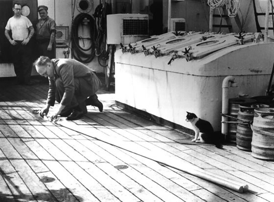
Unlike Stommel, Swallow had the relevant practical knowledge and resources to start work on the construction of the first floats in 1955. Aluminium scaffolding poles were used as they could withstand compression in seawater at depth and were readily available. To reduce the thickness of the aluminium the tubes were thinned in caustic soda – two 3-m lengths of tubing provided sufficient buoyancy for the float to be able to stabilise at 1000 m with a precise negative buoyancy of 38 g. The sound source used to track the float was a simple electronic circuit that produced 10 kHz signal, which was sealed within the aluminium tubing.
Floats were initially tracked using two hydrophones attached fore and aft of an attendant ship. As the ship’s heading changed the separation and convergence of signal arrivals gave the position of the float relative to the ship. At this time however, navigation over large parts of the ocean was still reliant on sun and star sights, dead reckoning and taking radar fixes on moored buoys and positions relative to submerged topographic features.
Swallow’s experiments indicated that real ocean currents did not always behave in the way suggested by theory. These floats revealed for the first time the mesoscale currents that are now known to populate the open ocean.
![John Swallow assembling a float on RRS Discovery II, watched intently by two matelots and the ship's cat]()
John Swallow assembling a float on RRS Discovery II, watched intently by two matelots and the ship's cat
- In the 1960s and 1970s SOFAR floats were developed and used extensively, especially with the advent of Autonomous Listening Stations (ALS) in the late 1970s.
Work continued on the floats with improvements to design and tracking methods. The lifespan of floats was increased (from ~5 days to ~50 days) through switching from continual sound signal transmission to intermittent signals (Swallow and Hamon, 1960). However, floats would need to be tracked for much longer than weeks if they were to provide insight into mean ocean circulation.
Major developments were made in the late 1960s and early 1970s. The first was the development of floats that transmitted a low-frequency sound (500-600 Hz) that could be tracked through the SOFAR channel (Rossby and Webb, 1970); an evolved version of Stommel’s initial idea. Trials using the US Airforce’s shore-based array of hydrophones demonstrated that float positions could be tracked across most of the northwest Atlantic over ranges of up to 1000 km to within 3-5 km.
The successful trials of the SOFAR floats led to the Mid-Ocean Dynamics Experiment (MODE; MODE Group, 1978). During this experiment an array of MODE SOFAR floats designed to drift at 1500 m for 1 year were deployed and tracked by hydrophones in Bermuda, Bahamas, Grand Turk and Puerto Rico that recorded their low frequency (~270 Hz) signals. The experiment was remarkably successful with some of the floats lasting 2 years.
However, this approach had the drawback that floats were restricted to particular depth horizons and so vertical current structures could not be resolved. With improvements to float electronics, Swallow was able to develop the ‘MiniMODE’ system (Swallow et al., 1974). This ship-based system allowed an array of floats with transponders to be tracked simultaneously as each had their own assigned frequency (5.0-6.5 kHz range). Through this array current structure could be observed over wider depth ranges within 70 km of the ship. Tracking was later achieved through use of master and slave floats instead of a ship. While SOFAR floats marked a significant progression in float evolution, at this time data were still largely restricted to mesoscale oceanographic features.
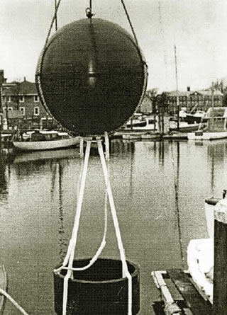
![Prototype SOFAR float in Woods Hole in the late 1960s. (Photo courtesy of Tom Rossby). The sphere housing the electronics and battery has a diameter of 1m, with the transducer hanging below. See Rossby & Webb 1970.]()
Prototype SOFAR float in Woods Hole in the late 1960s. (Photo courtesy of Tom Rossby). The sphere housing the electronics and battery has a diameter of 1m, with the transducer hanging below. See Rossby & Webb 1970.
- Autonomous Listening Stations (ALS)
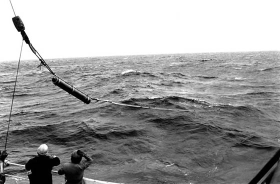
- The geographical constraints imposed by the use of shore-based listening stations were later relaxed by the development of moored Autonomous Listening Stations (ALS; Bradley, 1978). These consisted of subsurface moorings fitted with hydrophones, which extended coverage to the Gulf Stream and eastern Atlantic. In the mid-1980s float design was altered again to allow floats to go deeper. Pressure cases were made from glass spheres instead of aluminium tubing, which allowed floats to be tracked as deep as 3000 m at ranges of 1000 km (Gould, 1982). The transmission and tracking life of floats had become more of the order of years rather than weeks or months.
![JAn autonomous listening station being deployed from RRS Discovery in the mid 1980's. The ALS consists of a 10m hydrophone unit (furthest from the ship) and recording unit (cylinder above the hydrophone). The ALS was deployed at a depth of approximately 1000m on a mooring.]()
An autonomous listening station being deployed from RRS Discovery in the mid 1980's. The ALS consists of a 10m hydrophone unit (furthest from the ship) and recording unit (cylinder above the hydrophone). The ALS was deployed at a depth of approximately 1000m on a mooring.
- RAFOS floats began to be used in the late 1980s. These could be tracked using satellite systems, which greatly increased float life and the range over which floats could be traced.
Tom Rossby and colleagues made further developments to float design in the late 1980s by essentially inverting the SOFAR system (Rossby et al., 1986; Rossby et al., 1993). Put simply, they transferred the cumbersome sound sources to the moorings and fitted the floats with signal receivers and recorders. So the RAFOS float would triangulate its position based on the detected arrival times of signals from three sound sources, each one transmitting an 80 second long tone at 260 Hz on a precisely timed schedule. The float could then transmit the data back to Argos satellite system after surfacing at the end of its mission. The use of satellites allowed a greater coverage for float tracking than was available previously through the use of discrete listening stations but was still confined to an ocean basin scale.
Floats were also built that could follow density rather than pressure surfaces by the addition of a compressible element (Rossby et al., 1985).
The potential of floats to obtain more data than just ocean current trajectories was realised and some floats were adapted to take additional measurements including temperature and vertical water velocities.
The first measurement made by the floats, in addition to tracking ocean current velocities, was temperature (Pochapsky, 1963). This was followed by the customisation of some floats with angled fins. These fins meant that as water passed the float vertically, the float would rotate. This rotation was sensed by a magnetic compass and this was used to the study internal waves and upwelling through the measurement of vertical water velocities (Voorhis, 1968). Some floats were able to adjust their buoyancy, allowing them to measure vertical temperature gradients and the separation of density surfaces. This enabled scientists to study changes in stratification (Price, 1996; Rossby et al., 1994). Among these derivatives of the SOFAR and RAFOS floats were floats that could also measure electromagnetic fields (Sanford et al 1995).
Extensive use of both SOFAR and RAFOS floats was made primarily by research groups in the USA, France (Ollitrault,1994) and Germany (Zenk et al 1992).
![The largest version of a RAFOS float ever built, about 2.2 meters long. It includes a pump mechanism that forces it to float up and down to neighboring density surfaces (Rossby et al., 1994).]()
The largest version of a RAFOS float ever built, about 2.2 meters long. It includes a pump mechanism that forces it to float up and down to neighboring density surfaces (Rossby et al., 1994).
- Technology progressed quickly in the late 1980s/early 1990s with autonomous float deployments reaching a global scale, firstly with the ALACE float and then the MARVOR and PROVOR floats.
In the late 1980s, interest in the role of ocean circulation in the regulation of earth’s climate was at the forefront of oceanography. The result was the international World Ocean Circulation Experiment (WOCE), which in addition to satellite derived data and direct observations required global coverage of the World Ocean with subsurface floats.
ALACE floats
Acoustically tracking floats lacked the global scope needed to meet these new demands. Thus, Russ Davis and Doug Webb responded by developing the Autonomous Lagrangian Circulation Explorer (ALACE; Davis et al., 1992) . The pioneering feature of the ALACE float was that the otherwise neutrally buoyant float was able to adjust its buoyancy through inflating and deflating an external bladder. This allowed the float to repeatedly surface (typically every 10 days) and then return to depth and drift with subsurface ocean currents. When at the surface the float was able to be tracked by the Argos satellite system and transmit back data. The cycle would repeat for as long as the float’s batteries lasted, which could be several years.
The first ALACE floats to contribute to WOCE were deployed in the Drake Passage in 1990 and were set to drift at 1000 m depth. In total 1110 ALACE floats were deployed during WOCE. During the 1990s, the ALACE floats started to carry CTD sensors (P-ALACE) and transmit temperature and salinity depth profiles each time they surfaced (Sherman 1993).
The ALACE design had some limitations, however. While the ALACE float is able to adjust its buoyancy to surface in an hour or two at a vertical velocity of 10-20 cm/s or sink at a rate of about 5 cm/s, it cannot profile downwards from its drift depth. The float’s energy efficiency was compromised by the high pressure pump used with the external bladder to alter buoyancy and the internal oil bladder (the reservoir used to fill the external bladder) ruptured at high accelerations and thus the float could not be deployed from aircraft or from ships moving at speed.
MARVOR and PROVOR floats
The French MARVOR float was first deployed in 1994. A similar external bladder mechanism to that of the ALACE float enables the MARVOR to surface at regular intervals. Unlike the ALACE floats, however, MARVOR floats are tracked acoustically in the same way as RAFOS floats except that, rather than the data being obtained at the end of the float's mission, MARVOR floats transmit their recorded signal arrival times each time they surface (Ollitrault et al 1994). A profiling version of the MARVOR float was later developed, named PROVOR.
- The goal of developing a global array of 3000 profiling floats was reached in 2000.
The first Argo floats were deployed in 2000 and the array consisted of a combination of P-ALACE and PROVOR floats as part of the international co-operative effort. Initially, the array provided CTD profile data and subsurface ocean current data but continued development means that the current technology of newly deployed floats includes a growing range of sensors including, for example, oxygen probes, CO2, nitrate, chlorophyll and backscatter sensors.
Scientists and engineers continue to work together to enhance sensor stability, float battery life, and communication bandwidth (therefore enabling higher resolution data to be transmitted) thus maintaining the current and exciting science contribution that Argo makes to global oceanography. The initial programme goal of deploying 3000 floats was achieved in 2007 and the millionth profile was reached in 2012.
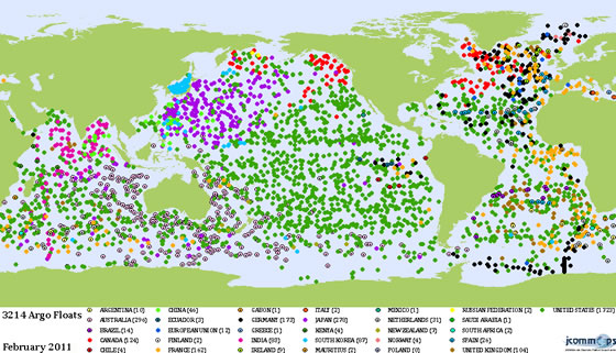
![Status of the global Argo sampling array at the end of February 2011 colour coded by country that launches the float.]()
Status of the global Argo sampling array at the end of February 2011 colour coded by country that launches the float.
- Float technology continues to be improved and advanced with changes in communication systems and sensors.
The modern array consists mainly of PROVOR (Ifremer, Kannad), APEX (Webb Research Corporation) and SOLO (Scripps) floats, new generation floats ARVOR (descendent of the PROVOR) and SOLO-II (upgrade of SOLO) and the newly developed Ninja (JAMSTEC) float.
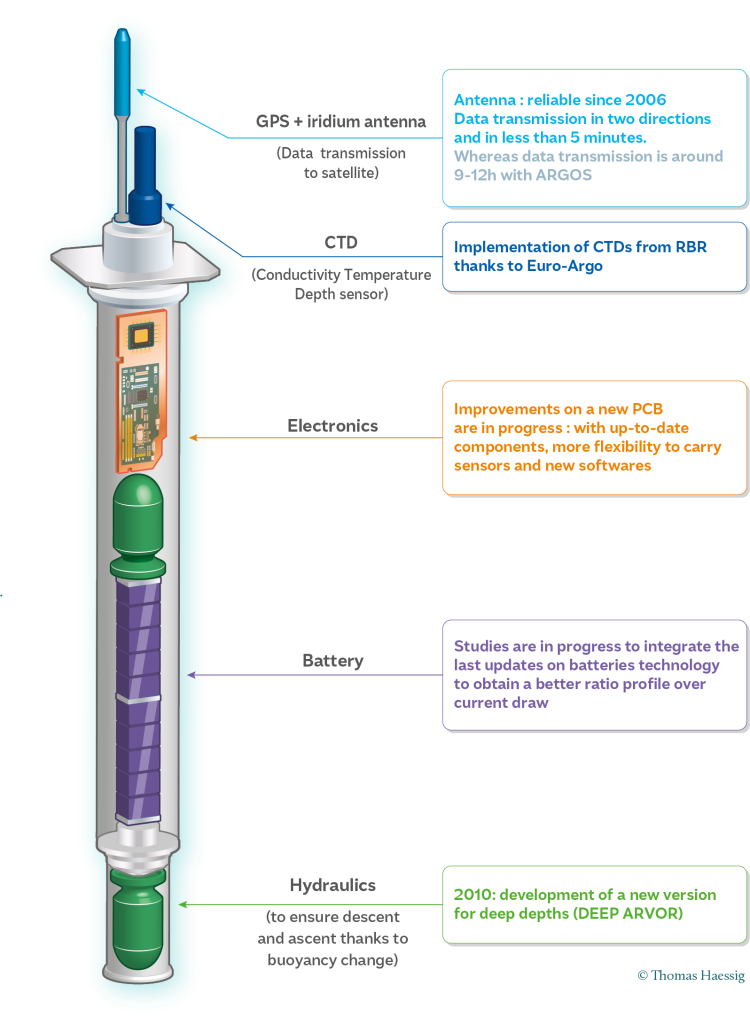
Scientists and engineers continue to work together to improve float efficiency, reliability, accuracy and lifespan. Some recent developments include:
- using the iridium transmission system
- developing biogeochemical sensors
- near-surface temperature measurements
- ice detection and avoidance software/li>
- deep profiling floats capable of sampling to 6000 dBar
The European Union funded Euro-Argo E-AIMS project is an international collaboration to develop and enhance new float technologies.
Modern Argo floats control their own buoyancy to complete their mission cycle of ~1000 m depth drift phase, and 2000 m profile to the surface. Older float designs, such as the ALACE floats, used pumps with an internal bladder and high pressue pump combination but could not sink any deeper than their drift phase depth. Modern floats use a simpler single-stroke pump that is more efficient and more reliable. This allows floats to profile depths deeper than their drift depth, which is essential to complete the park-and-profile mission cycle.
![]()
Modern Argo float design