RAFOS floats
Tom Rossby and colleagues made further developments to float design in the late 1980s by essentially inverting the SOFAR system (Rossby et al., 1986; Rossby et al., 1993). Put simply, they transferred the cumbersome sound sources to the moorings and fitted the floats with signal receivers and recorders. So the RAFOS float would triangulate its position based on the detected arrival times of signals from three sound sources, each one transmitting an 80 second long tone at 260 Hz on a precisely timed schedule. The float could then transmit the data back to Argos satellite system after surfacing at the end of its mission. The use of satellites allowed a greater coverage for float tracking than was available previously through the use of discrete listening stations but was still confined to an ocean basin scale.
Floats were also built that could follow density rather than pressure surfaces by the addition of a compressible element (Rossby et al., 1985).
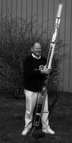
The largest version of a RAFOS float ever built, about 2.2 meters long. It includes a pump mechanism that forces it to float up and down to neighboring density surfaces (Rossby et al., 1994).